Tuesday, February 16, 2010

Remote Support Not Just For IT Guys Anymore

By: Todd VanGilder – Project Manager, CLA

In our line of work a big part of the job is getting the system up and running at the customer site.  Sometimes you are providing the customer with a turnkey system, and you do a complete runoff and customer acceptance on the shop floor prior to shipping.  In these situations onsite installation is clearly defined and after a few days on site you are up and running.  However, often you are only providing a piece to the puzzle.  When the pieces come together and things don’t work, suddenly the software you wrote, and hardware you provided, is being used to debug the overall system. But hold on a minute, we are suppose to be using the other pieces to debug our piece.  It is the proverbial “chicken or the egg”.  A common solution to this problem is to have all the players available on site for the entire installation process. In this scenario you may spend days or weeks on site, providing what may only amount to a few hours of support.  Perhaps a better solution is remote support ?  Remote monitoring/control applications like “LogMeIn” ,Web Cams, VPN’s and centralized source code control make it a viable option.

Software applications like “LogMeIn” allow you to view and take control of another PC (customers test stand in this case). Some of the advanced features of this software include drag and drop file transfer, performance monitoring, and remote to local audio.  Tools like this allow you to be available to your customer in smaller more sporadic time slices. This prevents the customer from having to spend unnecessary money while you sit on-site waiting for somebody else to troubleshoot their piece.

Sometimes, remote control and monitoring of the test stand does not tell the entire story. You may also need to see, the test fixture, and hear what is going on.  Today's webcams are relatively inexpensive and come with integrated microphones.   A picture is worth a thousand words, and with a few strategically placed cameras you can get the whole story.  Cameras are often a part of the customer requirements, and even when they are not the added value is quickly evident.

What about all that code you are modifying both remotely, on the test stand, and on your local computer?  How do you keep it under control?  We use Subversion for source code control with the TortoiseSVN windows client.  The challenge to using source code control is providing access to all the remote systems. That is where the VPN (Virtual Private Network) comes in, it allows us to access the repository from anywhere.  Our brilliant “WTI IT Guy”,  has setup access to our VPN through a web browser so it is easy to login from any computer connected to the internet. Once we are connected to the VPN committing and updating code works just like it does from our desk.

By utilizing remote support we are able to save our customers money by reducing on site time and travel expenses.  Another benefit from using the remote support for onsite startup is that all the tools are in place for fast response to warranty issues or software upgrades.  In addition, the customer has the ability to remotely monitor/control the operational system them self.

This solution is not for everybody and it has to be planned in advance so the system is quoted correctly and shipped with the proper tools in place.  More often than not, you will eventually make an on onsite visit.  The difference is, when you make the onsite trip you will have a clearly defined agenda, and the overall system will be in a much better place.

Thursday, October 29, 2009

Selecting the Correct Voltage Input Device for Fast High Channel Count Applications

By: Todd VanGilder – Project Manager, CLA

Over the years NI has come out with many different hardware platforms including, but not limited to: PXI, CompaqDAQ, CompaqRIO and Modular instruments. However, when dealing with fast scanning high channel count voltage measurements (200 plus) SCXI is still the best option.  A matrix/multiplexer module and a modular DMM is another option, but even with the fastest switching modules available this combination cannot compete with the available SCXI solutions; in reference to scanning speed. If accuracy is more important than speed then the DMM/switch option is a viable solution. For the remainder of this article I will focus on determining the correct SCXI devices based on voltage levels, filtering and scanning speed.

Once the SCXI platform has been selected there are still more decisions to be made. There are three 32-channel differential input multiplexer modules to choose from:  SCXI-1100, SCXI-1102(B)(C) and the SCXI-1104(C).  The first criteria we will be looking at are the maximum input voltages being measured, for this article we will focus only on DC levels. The input voltage range for both the SCXI-1100 and SCXI-1102 is ±10 VDC and both have selectable gains that allow them to accurately measure volt and milli volt sources. The SCXI-1104’s input voltage range is ±60 VDC and has a fixed gain of .1 making it more suitable for mid level voltages, like in automotive applications. However, this does not tell the whole story. Since they are referred to as differential measurement one might be inclined to think that as long as the difference between the CH+ and CH- does not exceed the input range of the device all is good, but this is not the case.  Both inputs (CH+, CH-) must remain within the voltage input range of the device in reference to CH GND.  For example, if you want to measure the voltage drop across a resistor in series with the 12 volt supply line of a DUT, and you expect the voltage drop will be milli volts, you would not be able to use an SCXI -1100 or the SCXI-1102, since both the high and low side measurement exceed ±10 VDC in reference to CH GND.  If the purpose of the previous example is to determine the DUT’s current draw, you have a few options.  If possible you could place the series resistor on the ground line of the DUT and use either the SCXI-1100 or SCXI-1102 to determine the current draw.  If you are only looking for an indication that the DUT is drawing current you could use an SCXI-1104, the calculated current would not be very accurate since the SCXI–1104 was not designed for milli volt measurements. A third option would be an SCXI-1125, the isolated amplifiers used on the SCXI-1125 can convert a small signal riding on a high common-mode voltage (±300 VDC) into a single-ended signal with respect to the SCXI-1125 chassis ground.  The SCXI-1125 only has 8 channels; in a high channel count application this will increase your cost and footprint by a factor of at least 4.

Once you have limited your choices based on voltage the next thing you might consider is the low pass filtering options.  If you are measuring DC levels with no interest in the frequency content of the signals the SCXI-1100 has a 4 Hz cutoff filter and the SCXI-1102 and SCXI-1104 have 2 Hz cut off filters. If you are interested in the frequency content of any of the signals then you need to select the appropriate SCXI module. The SCXI-102B has a 200 Hz filter and the SCXI-1102C and SCXI-1104C have 10K Hz filters. The SCXI-1100 cutoff frequency is selectable via jumpers for: no filtering, 10k Hz and 4 Hz.  However, the filtering selected for the SCXI-1100 changes the rate at which it switches channels, which affects the effective sampling rate. This leads us to the last consideration we will look at for selecting the correct device, the required sample rate.

Although the SCXI modules are strictly signal conditioning/multiplexing, and the AD is located on the multifunction DAQ card, the sample rate of the AD often is not the limiting factor when determining the effective sample rate of the system.  All input channels of the SCXI module are multiplexed (switched) into a single analog input channel of the E/M Series DAQ device. The maximum multiplexing rate of SCXI is 333k Hz. Therefore, if you are scanning 10 channels your max sample rate is 33.3k Hz and with 512 channels (max per DAQ device) 650 Hz would be your max sample rate.  If you needed to verify the duty cycle of a PWM signal and you were scanning 512 channels the highest frequency signal you could hope to accurately measure would be about 65 Hz, in order to define the signal with at least 10 data points. Obviously this assumes that the cutoff frequency of the hardware filter of the SCXI module is greater than 65 Hz. The SCXI-1100 scan rates vary with the selected band pass filter as follows: 166k Hz at full bandwidth, 6.6k Hz with 10k Hz filter and 3 Hz with the 4 Hz filter.  Both the SCXI-1102(B)(C) and SCXI-1104(C) multiplex at 333k Hz.  A combination of multiple DAQ cards and multiple SCXI chassis can be utilized to give the desired scan rates for the number of channels needed in the system.  Additionally the SCXI–1125 mentioned earlier can be configured in parallel mode, which allows the use of a different DAQ card for each SCXI-1125 in the SCXI chassis.

There are a lot of factors to consider when selecting the correct analog input device for your system requirements. I have only touched on a few of them in this article.  It can be very costly to discover the hardware limitations of your system after the build is complete.  I always recommend consulting your NI sales rep or an Alliance partner to help insure that the proper hardware is selected.

Thursday, April 30, 2009

What is the Best Software Development Method?

By: Todd VanGilder – Project Manager, CLA

There are many software development methodologies; which one is the best? I believe there is only one answer to this question; the method that best fits your customer and your company. The method you select should be decided on a per project basis. There are basically two categories of software development methodologies Agile and Plan- Driven.

The Agile home ground:
· Agile, knowledgeable, collocated, collaborative developers
· Empowered customers
· Reliance on tacit interpersonal knowledge
· Largely emergent requirements, rapid change
· Refactoring inexpensive
· Smaller teams, products
· Premium on rapid value

The Plan- Driven home ground:
· Plan-oriented developers; mix of skills
· Mix of customer capability levels
· Reliance on explicit documented knowledge
· Requirements defined early; largely stable
· Refactoring expensive
· Larger teams, products
· Premium on high-assurance

As a general practice, The Plan-Driven approach is our first choice when we start a project, it allows us to work with our customer at the beginning of a project to developed a specific scope of work and to charge a fixed fee for that work. We typically regard this as a best practice because it allows us to minimize the uncertainty and therefore manage some of the risk prior to starting the project. However, our corporate culture does allow us flexibility in the right situation. If the customer is early in their development phase, and therefore doesn’t have a clearly defined requirements document, then our best option is to work with the customer and develop the specification as the product progresses through the design phase.

My last three projects were “Cycle Testers” for automotive electronic modules. The “Cycle Tester” was capable of loading, exercising and monitoring multiple modules simultaneously, during durability testing. All three projects had the following challenges: no clearly defined customer for the module, incomplete firmware for the module, incomplete test requirements and aggressive timelines. When your customer is developing their product in parallel with the development of the testers it would be foolhardy to take a Plan-Driven approach. An Agile approach does not mean you do not have a plan it simply is a more adaptive plan vs. a more predictive plan.

The Agile Manifesto states:

We are uncovering better ways of developing software by doing it and helping others do it. Through this work we have come to value:

Individuals and interactions over processes and tools
Working software over comprehensive documentation
Customer collaboration over contract negotiation
Responding to change over following a plan

That is, while there is value in the items on the right, we value the items on the left more.

One of the challenges of using an Agile development plan is quoting a job that’s scope is not clearly known by the customer. One option is to assign a fixed cost to those things that are known, and negotiate what is a scope change and what isn’t. The problem is this contradicts the agile manifest to collaborate over negotiate. I believe the answer is to quote the project as a T&M (Time & Materials). If the hardware and build portion of the project is clearly defined then provide a fixed cost quote for that portion of the job.

One of the criticism of the Agile approach, and T&M’s, is they can be used as a means to bleed money from customers through lack of defining a deliverable. My response to that is, there has to be a trust between the customer and the client or the project is doomed. I believe it is our job to demonstrate to potential customers through our actions and past performances that we are worthy of their trust. It starts with the sales person, but it is everyone’s responsibility. The truth is if you are dealing with a company that’s goal is to bleed customers they are going to bleed you no matter what type of development process or P.O. you have agreed to. IMHO two of the most important attributes to look for when selecting a business partner is competency and honesty. If you can form this type of a relationship with your customers then everyone can focus on what is important, delivering a good product; not negotiating scope changes.

I believe the Agile method lends itself very nicely to LabVIEW and NI hardware platforms. Agile is about spending more time coding and less time documenting. When LabVIEW coding is done properly it inherently provides a certain level of documentation. There is also a premium on speed; I would certainly argue there is no faster programming environment then LabVIEW. Also, flexibility and adaptability are both attributes of LabVIEW and Agile. Furthermore the NI hardware platforms and drivers also possess the attributes an Agile methodology covets.

Monday, March 9, 2009

A More Universal Approach to Wait Cases

By: Dave Graybeal – Project Engineer, CLD


INTRODUCTION

The purpose of this particular blog is to help show an example of something that the WTI Clarkston Office has developed to help decrease the number of cases in our code and help speed up the application development process(even if only slightly increased). In this Blog I will be talking about the Typical Wait Case found in many applications and how we have replaced those wait cases with a single more Universal Wait Case in their place. These examples are shown using a Queued Master Slave State Machine with a String Queue. Other Types of Queues (Variants, Enums, etc.) could also be used but may require some additional code not shown in the Figures below.


TYPICAL WAIT CASE

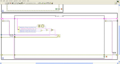
The picture below (Figure 1) shows a common wait case. The key elements found in a wait case are the loop rate control (which controls the processor usage during free spin), the start time (typically set in the case that sent the application to this wait), the wait time (commonly found as a hard coded constant like shown in the picture) and the case decision (with the current wait case wired to the false condition and the destination case hard coded and wired to the true condition). Many times in an application you may find the need for different destinations and/or different amounts of wait time. Using wait cases in this way create the need to have multiple cases in a single application that all provide the similar functionality. This in turn makes the code harder to follow and makes for a longer case list (which may already be long enough)

See larger Image


Figure 1


MAIN CLUSTER SETUP

The picture below (Figure 2) shows an example of how the WTI Clarkston Office uses a single Cluster Shift Register to carry around our data. We also break down the cluster into the subcategories; Application Control, Application Timing, Application Data, and Static Inputs). The items relevant to this Blog are the items shown underneath the Application Timing Category. If you are already using a single cluster shift register then you would need to add a cluster within it that contains the following:
1. String – “Next Case”
2. U32 – “Start Time (ms)”
3. U32 – “Wait Time (ms)”
4. U32 – “Loop Rate (ms)”
Each of these items satisfies one of the key elements described in the Typical Wait Case section.

See larger Image


Figure 2


UNIVERSAL WAIT CASE

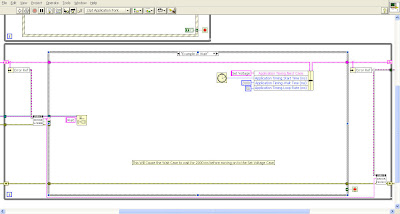
This case shown below (Figure 3) shows the Universal Wait Case. Each item required by the key elements is pulled from the MAIN CLUSTER and acted upon accordingly. The code is very similar to that found in the Typical Wait Case, except that the Hard Coded Components are replaced with controllable items found within the cluster instead. This allows for this single Wait Case to be used for multiple desired waits throughout the same application. In turn this makes the flow a little easier to follow and reduces the number of cases found in the application.

See larger Image


Figure 3


CALLING THE UNIVERSAL WAIT CASE

To use the Universal Wait Case simply wire the Desired values into the Bundle Cluster Node(as shown below in Figure 4) and Enqueue “Wait” into the Queue. As a note, to save some more space where loop rate is not as important to have programmatic control over you can simply use a default value for the “Loop Rate (ms)” control in the creation of the Shift Register and simply don’t wire a new value into it.

See larger Image


Figure 4


SUMMARY

As simple of a change as this is, it has certainly proved to be value added to me and my colleagues. In the end I believe it saves time recoding the wait case multiple times (even if it only means a time saving of duplicating a previously created wait case and changing the hard coded values), and promotes re-usable code. I hope that this blog post has been helpful to everyone.

Expect more on our Queued Master Slave State Machine Template to come in the future.

Saturday, January 17, 2009

Welcome to WTI Guy

Welcome to WTI Guy, a collaborative blog from the Employee’s of Wineman Technology, Inc (WTI), an NI Alliance Partner. I have been thinking of starting a blog for a while know, but like many others I am sure, I was not confident I would have the time to keep up with it or enough to say (that people wanted to hear anyway). This Blog is my solution; hopefully a collaborative blog does not offend or unbalance the blogosphere.

At “WTI Guy” you will get your share of LabVIEW tips and tricks and design pattern discussion, but I also hope we can provide something more. WTI has over 40 employees that live LabVIEW and NI five days a week, in various capacities. This blog will also be a collage of the insights, observations and commentary of Project Managers, Project Engineers, Electricians, Sales and Office personnel.

Look for more postings soon; and hopefully frequently.